- English
- 简体中文
- Esperanto
- Afrikaans
- Català
- שפה עברית
- Cymraeg
- Galego
- 繁体中文
- Latviešu
- icelandic
- ייִדיש
- беларускі
- Hrvatski
- Kreyòl ayisyen
- Shqiptar
- Malti
- lugha ya Kiswahili
- አማርኛ
- Bosanski
- Frysk
- ភាសាខ្មែរ
- ქართული
- ગુજરાતી
- Hausa
- Кыргыз тили
- ಕನ್ನಡ
- Corsa
- Kurdî
- മലയാളം
- Maori
- Монгол хэл
- Hmong
- IsiXhosa
- Zulu
- Punjabi
- پښتو
- Chichewa
- Samoa
- Sesotho
- සිංහල
- Gàidhlig
- Cebuano
- Somali
- Тоҷикӣ
- O'zbek
- Hawaiian
- سنڌي
- Shinra
- Հայերեն
- Igbo
- Sundanese
- Lëtzebuergesch
- Malagasy
- Yoruba
- Español
- Português
- русский
- Français
- 日本語
- Deutsch
- tiếng Việt
- Italiano
- Nederlands
- ภาษาไทย
- Polski
- 한국어
- Svenska
- magyar
- Malay
- বাংলা ভাষার
- Dansk
- Suomi
- हिन्दी
- Pilipino
- Türkçe
- Gaeilge
- العربية
- Indonesia
- Norsk
- تمل
- český
- ελληνικά
- український
- Javanese
- فارسی
- தமிழ்
- తెలుగు
- नेपाली
- Burmese
- български
- ລາວ
- Latine
- Қазақша
- Euskal
- Azərbaycan
- Slovenský jazyk
- Македонски
- Lietuvos
- Eesti Keel
- Română
- Slovenski
- मराठी
- Srpski језик

How Can a Pneumatic Conveying System Cut Dust, Downtime, and Material Loss?
Abstract
Moving powders, pellets, and granules sounds simple until you’re dealing with dust clouds, clogged chutes, segregation, broken product, and operators babysitting transfer points all day. A well-designed Pneumatic conveying system moves bulk material through enclosed pipelines using controlled airflow, helping plants stay cleaner, safer, and more consistent while reducing manual handling.
This guide breaks down the decisions that actually matter to performance and operating cost, from vacuum vs pressure to dilute vs dense phase, filtration, airlock selection, and pipeline routing. It also includes a practical checklist, a comparison table, and an FAQ so you can move from “we need something that works” to a clear, low-risk specification. Examples and recommendations reflect common industrial conditions and the engineering approach used by Shandong Yinchi Environmental Protection Equipment Co., Ltd.
Table of Contents
- Outline
- What Problems Does Pneumatic Conveying Solve
- How a Pneumatic Conveying System Works
- Vacuum Conveying vs Pressure Conveying
- Dilute Phase vs Dense Phase
- Key Components That Decide Reliability
- Design Checklist Before You Buy
- Energy and Operating Cost Levers
- Dust Control and Safety Considerations
- Commissioning and Maintenance Plan
- Real World Use Cases
- FAQ
- Conclusion and Next Steps
Outline
- Identify your biggest pain points and what “success” looks like on the floor
- Understand the airflow-and-solids basics so proposals are comparable
- Pick the right conveying mode for distance, layout, and pickup points
- Choose dilute or dense phase based on product fragility and capacity
- Lock in reliable components that match your material behavior
- Use a checklist to reduce risk before fabrication and installation
- Plan for dust control, safe operation, and maintainability from day one
What Problems Does Pneumatic Conveying Solve
If you’re considering a Pneumatic conveying system, you’re probably not doing it for fun. You’re doing it because your current transfer method is costing you time, product, and patience.
- Dust at transfer points that coats equipment, triggers housekeeping alarms, and creates uncomfortable working conditions
- Material loss and contamination from open conveyors, leaks, or frequent cleanup
- Bridging and clogging in chutes, hoppers, and screw feeders due to inconsistent flow
- Inconsistent batching caused by segregation, spillage, or unstable feed rates
- High labor dependence where operators must intervene to keep material moving
- Product damage such as pellet breakage, powder attrition, or excessive fines generation
- Layout constraints when you need to route around structures, across floors, or up to silos
Enclosed pipeline conveying helps because it reduces exposed transfer points and moves material with controlled air and pressure. That means fewer places for dust to escape, fewer places to spill, and fewer places for “mystery downtime” to hide.
How a Pneumatic Conveying System Works
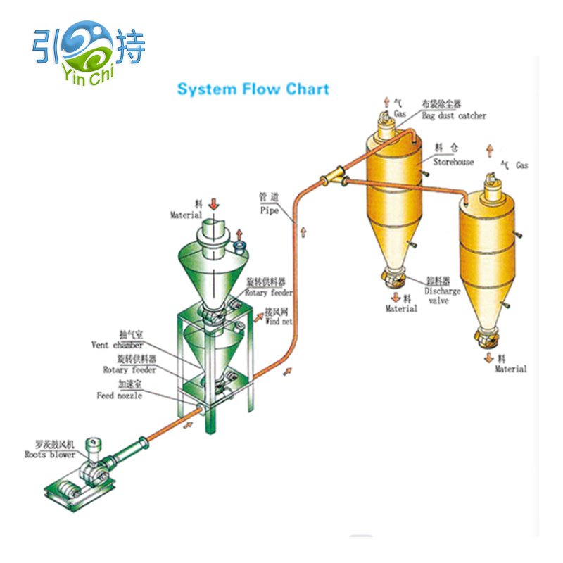
At a high level, a Pneumatic conveying system transports bulk solids through a pipe using a pressure difference and airflow. Material enters the conveying line at a pickup point, travels to a receiving vessel, and the air is separated from the solids by filtration.
What’s happening inside the pipe
- Airflow provides the driving force
- Solids are entrained or pushed along depending on the conveying mode
- Velocity must be high enough to prevent settling but not so high that it destroys product or wastes energy
- Bends, long runs, and elevation changes add resistance and affect stability
What you should demand from any design
- Stable conveying without surging, plugging, or “burping” at the receiver
- Predictable feed rate across shifts, seasons, and material lot changes
- Dust-tight operation with filtration sized for real production conditions
- Reasonable maintenance access to wear points and filters
Vacuum Conveying vs Pressure Conveying
One of the first choices is whether your conveying line should pull material (vacuum) or push material (pressure). Both can work well, but they solve different plant problems.
| Decision Factor | Vacuum Conveying | Pressure Conveying |
|---|---|---|
| Pickup points | Often better for multiple pickups into one receiver | Often better for one pickup feeding multiple destinations |
| Leak behavior | Leaks tend to draw air inward, helping reduce dust escape | Leaks can blow dust outward if not sealed well |
| Typical distances | Commonly shorter to moderate, depending on design | Commonly moderate to longer, depending on capacity and mode |
| Best for | Clean receiving, flexible pickup routing, tidy plants | Higher throughput, longer runs, robust delivery to silos |
| Complexity focus | Receiver filtration and vacuum source stability | Feeding device, pressure control, wear management |
A practical rule of thumb is to start with your layout. If you need to collect from several points and deliver to one place, vacuum solutions often simplify the network. If you need to deliver material to a distant silo or multiple bins, pressure conveying may be a better fit.
Dilute Phase vs Dense Phase
This is where many projects succeed or fail. The same Pneumatic conveying system can behave beautifully with one material and terribly with another if the phase choice is wrong.
Dilute phase
- Material is carried in a relatively high-velocity air stream
- Often simpler to control and can handle a wide range of powders and pellets
- Risk: higher velocity can increase wear, noise, and product attrition
Dense phase
- Material moves at lower velocity in a more “slug” or “plug” manner
- Often preferred for fragile products, abrasive powders, or when minimizing degradation matters
- Risk: may require more careful feeding, pressure control, and material-specific tuning
If your plant has issues like pellet breakage, too many fines, or visible erosion at bends, dense phase (or a lower-velocity strategy) becomes a serious candidate. If your top issue is simply reliable transport with straightforward control, dilute phase may be the fastest path to stability.
Key Components That Decide Reliability
Quotes can look similar on paper, but component choices reveal whether the supplier understands your material. Here are the parts that most often decide day-to-day performance.
- Feeding device such as rotary airlock valve, venturi, or pressure vessel feed, selected for leakage control and stable solids rate
- Air source such as blower, fan, or compressor, sized for the required pressure and flow with margin for filter loading
- Conveying line including pipe diameter, bends, and wear sections, designed to limit pressure drop and prevent settling
- Receiver and filtration including filter area, cleaning method, and dust discharge, designed for continuous operation without choking
- Controls and instrumentation including pressure sensors, differential pressure across filters, and interlocks that prevent runaway plugging events
For many factories, the airlock valve is a silent troublemaker. Too much leakage means unstable conveying, poor receiver separation, and unexpected dust. Too tight or poorly matched clearances can create heat, binding, and frequent stops. Match the airlock to your particle size, temperature, abrasiveness, and required sealing level.
Design Checklist Before You Buy
Use this checklist to compare proposals and reduce unpleasant surprises after installation. The goal is not perfection, it’s risk control.
- Material profile including bulk density, particle size range, moisture sensitivity, stickiness, abrasiveness, and temperature
- Capacity targets including average rate, peak rate, and how often peaks occur
- Distance and routing including total equivalent length, number of bends, vertical lifts, and available support points
- Pickup and discharge points including how many sources and destinations you need now and within two years
- Cleanliness standard including how much dust is acceptable around the receiver and what housekeeping looks like today
- Power and utilities including available electrical capacity and whether compressed air is stable and dry
- Wear management including bend style, replaceable wear sections, and access for inspection
- Maintenance access including filter change space, airlock service clearance, and safe isolation points
- Commissioning plan including test runs with your real material, not only with “typical” samples
If a proposal avoids these topics or answers them vaguely, that’s not a “nice-to-have” gap. That’s where your downtime will come from later.
Energy and Operating Cost Levers
Operating cost is not only about motor size. It’s about whether the system can move material at the lowest stable velocity and pressure for your specific conditions.
- Pipe diameter selection affects velocity and pressure drop dramatically
- Routing discipline such as fewer sharp bends reduces turbulence and wear
- Airflow control helps avoid over-blowing material just to “be safe”
- Filter sizing prevents high differential pressure that forces the air source to work harder
- Leak management at airlocks and connections reduces wasted air and unstable flow
A common hidden cost is running at excessive air velocity because the system is under-instrumented. With better pressure and filter monitoring, operators can trust the process, not their instincts, and you can keep the line in a stable, efficient window.
Dust Control and Safety Considerations
Dust is not only a cleanliness issue. Fine particles can become airborne easily, migrate into bearings and electrical cabinets, and create uncomfortable working environments. Enclosed conveying reduces the number of open transfer points, but dust control still depends on smart receiving and filtration.
Practical measures that make a visible difference
- Use a receiver with sufficient filter area so filtration stays stable during long runs
- Choose a filter cleaning method that matches your duty cycle and dust behavior
- Plan dust discharge so fines do not re-enter the workspace during emptying
- Seal connections and maintain gaskets to keep the system truly enclosed
- Keep inspection ports accessible so “small issues” don’t become sudden plugs
If your material is combustible or extremely fine, discuss plant-specific safety requirements early in the project. Good engineering is proactive: it assumes real-world variability and builds in protective layers rather than relying on perfect operator behavior.
Commissioning and Maintenance Plan
A Pneumatic conveying system should not require heroics. The easiest way to achieve that is to treat commissioning as part of the design, not an afterthought.
- Baseline test with your actual material at expected temperature and moisture range
- Velocity verification to confirm you’re above settling limits without over-accelerating
- Filter loading observation to confirm the cleaning cycle keeps differential pressure stable
- Wear inspection plan for bends and high-impact zones at defined runtime intervals
- Spare parts strategy focusing on airlock seals, filter elements, and wear sections
Most “mysterious problems” show up as patterns in pressure, filter differential pressure, and motor load. Instrumentation doesn’t need to be fancy, it needs to be placed intelligently and actually used.
Real World Use Cases
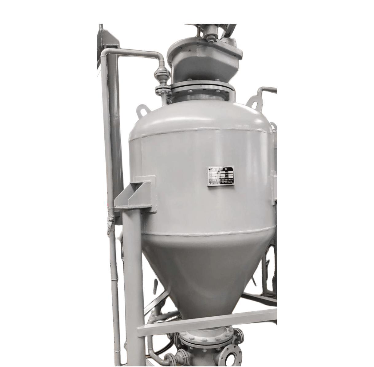
Here are common scenarios where plants choose pneumatic conveying and what they typically optimize for.
- Powder transfer to mixers prioritizes dust-tight pickup and consistent feed to protect batch quality
- Pellet conveying to silos prioritizes gentle handling and wear-resistant bends to reduce fines
- Bag dump stations prioritize local dust extraction and clean receiving to protect operators
- Multiple pickups into one process line prioritizes stable switching logic and balanced suction
The common thread is control of variability. Material changes. Ambient humidity changes. Operators change. The system must still deliver stable flow without demanding constant manual intervention.
FAQ
Q1. What information should I prepare before requesting a proposal
Provide your material name, bulk density range, particle size range, moisture sensitivity, temperature, desired capacity, distances, number of bends, and pickup and discharge points. If you have photos of current transfer points and the surrounding dust situation, that helps engineers design for reality rather than assumptions.
Q2. Will a pneumatic system damage fragile pellets or granules
It can if velocity is too high or bends are poorly selected. That’s why phase choice, routing, and bend design matter. When product integrity is critical, lower-velocity strategies and wear-managed routing can significantly reduce attrition.
Q3. Why do some systems plug even when the motor is powerful
Plugging is often caused by unstable feed, too many sharp bends, incorrect air-to-solids ratio, moisture-driven adhesion, or filter restriction that changes airflow during operation. More power does not automatically create stable conveying.
Q4. How do I reduce dust around the receiver
Focus on receiver filtration area, proper filter cleaning, sealed connections, and a controlled discharge method for captured fines. Dust issues usually come from undersized filtration or poor sealing rather than from “pneumatic conveying” itself.
Q5. Can one system handle multiple materials
Sometimes, but it depends on how different those materials are in density, particle size, and flow behavior. If you must handle multiple materials, ask for a design that defines stable operating windows and includes practical changeover and cleaning steps.
Conclusion and Next Steps
A Pneumatic conveying system is not a one-size purchase, it’s a process decision. When the phase, air source, feeding method, routing, and filtration are matched to your material and layout, you get cleaner floors, fewer interruptions, and more predictable production. When they’re not, you get dust, plugs, and a system everyone avoids.
If you want a design that fits your plant conditions and material behavior, Shandong Yinchi Environmental Protection Equipment Co., Ltd. can help you define a clear specification, compare conveying modes, and build a practical plan for installation and operation. Ready to reduce dust and stabilize transfer points? contact us to discuss your application and get a tailored solution.